Dear all,
With great sadness I have to let you know that Niels took a one way trip to the stars on October 17th 2012. Please remember him with a good glass of red wine one a bright starry night. Take care all of you, Marjoleine Noordhoek-Groen
Niels
November 2nd, 2012Bahtinov grabber without autofocus
September 29th, 2012Since most people likely do not use the autofocus function, Bahtinov Grabber without autofocus is a further simplification: it does not depend on the Ascom driver (.NET still required though).
You can download the latest Bahtinov Grabber without autofocus (32 and 64 bit in one zip) here Bahtinov Grabber without autofocus (6688).
Triboluminescence of sugar and fractoluminescence of glass
August 11th, 2012A very simple but quite surprising experiment:
- take a sugar cube to a very dark room
- smash it with a hammer (which is not an easy task in the dark!)
- look at the sugar cube and see what happens
You should be able to see a clear blue flash “inside” the sugar cube.
Though the effect is clearly visible, taking a photo is quite hard.
I used a very light sensitive lense (f/1.8) and the camera at the most sensitive mode (ISO 3200) and the blue light was still in the lower part of the histogram:
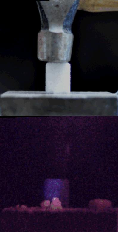
Above: hammer and sugar cube in normal light, below the sugar cube in the dark while being smashed with the shutter open for 3 seconds at f/1.8 and at ISO3200. The room was not perfectly dark, so besides the blue glow, you can still see the vice and the remains of the cube.
The effect is called triboluminescence, an apperently not-so-well understood optical phenomenon that occurs when crystals are rubbed. So when you use more force/energy in hitting the sugar, you should get more light. Therfore shooting a sugar cube may give better photos:
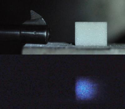
Sugar cube shot from the side with an air pistol, indeed producing more blue light than when crushed with a hammer.
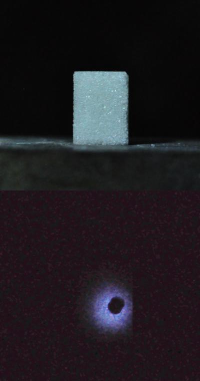
A sugar cube, shot from the direction of the camera. The triboluminescent light actually becomes a high speed flash itself. The dark spot is the pellet hitting the sugar.
I got to this subject, because a similar (though yellow) effect appeared in the mirror we shot with the .308 Winchester. However, when I smashed a piece of mirror with a hammer, no optical effect like in the sugar was visible at all. Some scientific papers seem to suggest that triboluminescence occurs in glass and that it has a Boltzmann like spectrum (similar to a glowing hot object). A more appropriate term may be fractoluminescnce in the case of glass: before it shatters, glass breaks at a very high speed, and the energy dissipated in a very small region of the material at the crack tip heats it up, and thermal photons are emitted (as confirmed by Elisabeth Bouchaud).
3D high speed photography
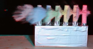
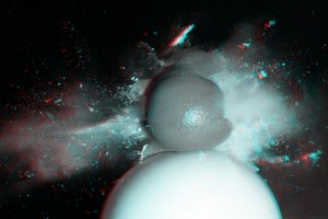
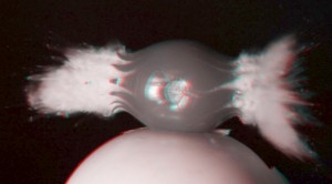
August 9th, 2012Flash photography lends itself perfectly for 3D photography: the flash ensures that the two photos that make up the anaglyph (stereo image) are taken at exactly the same moment in time. Simply place 2 cameras with the same focal length (preferably identical cameras with identical settings) and point them at the same scene.
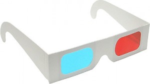
By using a simple Matlab script, the red and green+blue channels are mixed to make a 3D image that must be viewed with red-cyan (or red-blue) glasses.
When you first make black and white images of the two photos, you can make a black and white anaglyp. For some situations this is the only solution: take for example the bright red tomato. You simply cannot expect that to work with red-blue glasses (nothing will pass the blue filter).
Ultra-high speed photography: .308 Winchester
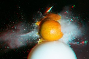
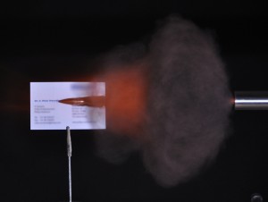
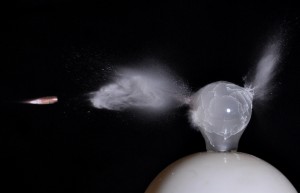
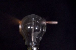
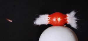
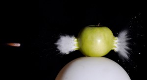
July 21st, 2012Some photo’s taken of the .308 caliber (DPMS LR-308, 150 grain Full Metal Jacket) at a muzzle velocity of about 860 m/s (3100 km/hour or 2820 feet per second), roughly 2.5 times the speed of sound. The light source was a home grown air-gap flash, triggered with a simple piezo microphone.
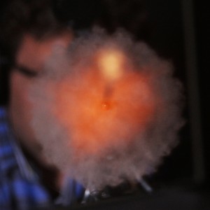
Note that vaporized tomato, orange and apple juice all are white instead of red, orange and green!
Rear wheel bearing replacement on Skoda Octavia II combi
July 1st, 2012A slight grinding noise in the back of the car was one of the very few things I did not like, after buying a nice six year old Octavia II (130.000 km). Having done a similar job on my 45 year old Volvo Amazon, I would hope that I would be capable of doing the same on a modern car.
After studying on the internet for several evenings I decided it was possible. Main challenges seemed to be getting the right tools (simple hexagon bolts and nuts seem to be old school, or the Volkswagen people just don’t like amateurs working on their cars), and a torque of “180 Nm plus 180 degrees” on the only bolt holding the rear bearing and thus the wheel to the car. The 180 Nm I could imagine: an arm of 1 meter and a force of 18 kilos, that does not sound too impressive, but how much elbow grease would the “plus 180 degrees” mean?
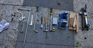
After getting what I thought were the the required tools I took off the rear wheel to double check if that would not get me halfway into the job finding out I was still missing something, ending up with a car that could not make it safely to the garage any more. And I was missing some equipment. Below is the final recipe for transplanting the old bearing for a new one:
Tools needed:
- telescopic socket wrench (17 mm)
- wheel stops (you are will be releasing hand brake while working on the car)
- car jack (2 tons)
- two adjustable axel stands
- torque wrench 1/2 inch, 20-200 nm
- small rope for suspending the caliper
- strong rope for pulling the breaker bar when removing the m14 caliper holder bolts
- Loctite (blue)
- Torx 30 bit (brake disk screw)
- pieces of wood
- claw hammer
- 1/2 inch socket wrench
- 1/2 inch (female) to 3/4 inch (male) adapter
- 1/2 inch breaker bar
- 3/4 inch breaker bar
- M18 XZN (Volkswagen tool T10162) 3/4 inch socket for axel bolt
- pair of callipers to measure the disk thickness
- M14 XZN 1/2 inch socket for caliper holder bolts
- M15 wrench
- M13 wrench
- old cloth
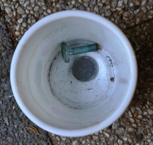
- bucket to store nuts and parts removed
- gloves (or do you?)
Parts needed:
- VKBA 3644, which is a flange with a bearing inside, new M18 XZN screw and dust cap. Several brands are available. I chose for SKF.
Work steps (took me less than two hours the first time):
1. place wheel stops behind, in front of wheels and release the hand brake
2. loosen the wheel nuts slightly
3. jack up the car as high as reasonably possible (you will need space for a 30cm breaker bar pointing down)
4. place axel stand (never trust the jack alone or bricks that can break) and lower car onto it
5. remove wheel nuts
6. remove wheel
7. remove two caliper bolts with a 13mm plus a 15mm spanner: place the spanners such, that you can squeeze them towards each other to generate the required force.
8. lift of the caliper and suspend it from a rope from the shocks, so there will not be a lot of force on the hydraulic line.
8. remove two caliper holder bolts: 14mm triple square (XZN) with 30 cm 1/2 inch breaker bar. If you do not remove this part than you cannot remove the brake disk and thus the bearing (nasty design). The breaker bar points to the floor. I use a rope attached to the end of the breaker bar, sat behind the car on the removed wheel, put my right foot on the axel and pulled with 2 hands on the rope, backwards. The nut was tightened with 90 Nm plus 90 degrees and may be corroded, so you will need some force.
The breaker bar was good for two reasons: lots of force and there was too little room to fit my socket wrench.
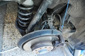
M14 XZN breaker bar in caliper holder bolt. The white rope is attached to the end of the breaker bar, so two hands can be used to pull, with one foot resting on the axel.
9. remove the small screw (Torx 30) keeping the brake disk in place
10. Knock off the brake disk. This took me quite some effort: I used a short piece of wood and a the backside of a splitting axe held to the edge of the disk. Be careful not to damage the disk doing so.
11. pull of the dust cap. I use a “claw hammer” and gently worked my way around. You will discard it and the flange too, so you can be brutal.
Finally the dreaded “180nm plus 180 degrees M18 XZN” is in sight!
12. To remove the M18 XZN:
- place a axel stand in front of the wheel nut, at a similar height (see photo). Use the M18 nut, extension and breaker bar and rest the extension on the axel stand, close to the breaker bar. This way the M!8 nut will only receive a rotational force and not a force perpendicular to the nut, which could result in big trouble (damage, injury).
I used a 70mm 1/2 inch breaker bar, which looked over sized when I got it, but that feeling will disappear soon: place the breaker bar and possibly and extension at “9 o’clock”. Place your foot on the end of the breaker bar and discover that that is not enough force. Next step is to stand on the breaker bar and discover you are not heavy enough. The jump up and down a little but and if you are lucky, there will be some movement. I was using a stainless steel pipe to get another half meter extension, and was seriously fearing the bear would break to peaces exploding with lethal energy in arbitrary directions. I was very happy to have spent my money on a Gedore breaker bar and an original Volkswagen M18 nut when the nut was finally out.
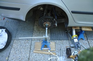
Unscrew the axel bolt by supporting the extension with an axel stand, and standing on the breaker bar.
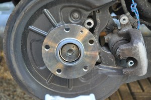
13. Pull off the flange plus bearing. Though it was rusted, it did not take me a lot of force to take it off and the axle was still shiny underneath.
14. Put on the new flange plus bearing. Be careful to put it on straight an make sure the axle is clean (rust, dust and sand). The first millimeters are tricky but the it should slide on smoothly.
15. And now for the “piece the resistance”: putting on the M18 axel bolt with “180 Newton meters plus 180 degrees”. Just dial in the 180 Nm and tighten the bolt (new bolt, do not use the old one!) until the thing goes click. Then place the axel stand again see photo), rest the 1/2 inch extension on it and place the breaker bar at “3 o’clock”. On the bolt there are several markings. Take note of the a marking and imagine it being rotated 180 degrees. Mental preparation is everything. After about 30 degrees most people give up, not you. I ended up standing on the extension bar with both feet, jumping up and down like it was a springboard until 180 degrees was reached. I estimate that must be between 800 and 1600 Nm, once to twice my weight on a 1 meter bar.
After this you are a member of the “180 Nm plus 180 degrees” and nothing can stop you now. Some small stuff:
16. – Hammer on the dust cap. Use a flat piece of wood to hold the new dust cap flat on the flange so you hammer it in straight and do not damage it with the hammer.
17. Place the brake disk back (of course you check the thickness: this would be the ideal moment to put on a shiny new one if required. 8 mm seems to be the lower threshold for replacement).
18. Screw in the brake disk holding screw torx30.
18. Place back the caliper holder (2x M14 XZN, 90 Nm plus 90 degrees, but I did it by guestimation to be honest). Apply some Loctite to prevent it from rattling loose.
19. Spread the caliper piston slightly with a rewind tool. It take a lot of force and the piston apparently needs to rotate while being pushed back.
19. Place back the caliper (do not forget to remove the rope) and tighten the two nuts (35 Nm) with some Loctite.
20. Put the wheel back on
21. Put on the wheel nuts
22. Engage hand brake
23. Jack up the car and remove axel stand
24. Lower the car and torque on the wheel nuts (110 Nm for aluminum rims)
25. Facing the wheel take two steps back, rub your hands in an old cloth and stand proud: you did it!
26. Get in the car and press the brake pedal several times. This will take the slack out of the piston that was pushed back.
27. Remove wheel stops and take it for a ride!
Phosphorescence of quartz
May 25th, 2012The inner glass tube of the air-gap flash so far was made of Pyrex. The spark has a temperature of about 30,000 degrees Celsius, so the flash gives the pyrex a horrible temperature shock (more than 30,000,000,000 degrees Celcius per second). Pyrex is a good choice, since it has a very low thermal expansion coefficient, causing a minimum of stress in the material when heating up. For the same reason Pyrex is also very popular in kitchens (glass that does not break in an oven) and telecopes (mirrors that need to keep their shape extremely accurately at a range of temperatures, for the Hale telescope they even tried quartz, but gave up and used Pyrex).
Still, after a random number of flashes the Pyrex tube tends to shatter to small pieces.
In comes quartz: it has an even lower thermal expansion coefficient (4e-7 m/mK, about four times lower than that of Pyrex).
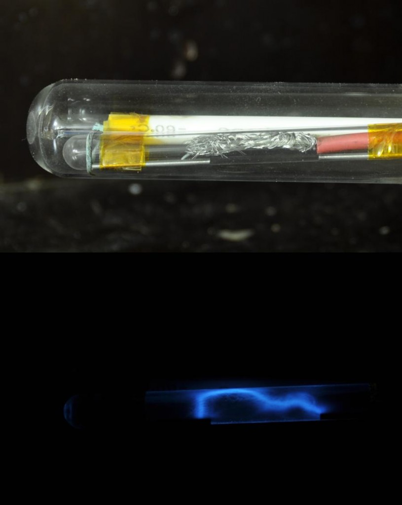
To my surprise the quartz tube has a beautiful blue afterglow for several minutes, which reminds me of Cherenkov radiation as seen in nuclear reactors. After some searching I found it is blue phosphorescence, caused by impurities in the quartz, cuased by the UV in the spark. It shows nicely how the spark went over the surface (different every flash).
Party time
April 3rd, 2012“DNA” of an air-gap flash: spectroscopy
March 31st, 2012The color of a light source can be unravelled into it’s principal components using a diffraction grating.
Each separate color (wavelength) is bent to a different position, resulting in a rainbow like image.
To best separate each color, a photo is taken of the light source behind a narrow slit. The resulting spectrum is an infite numbers of copies of that slit, spread out into a spectrum.
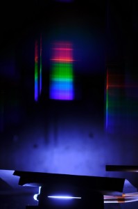
Setup, showing the slit below, with the spark gap behind it and the diffraction spectrum floating above in air
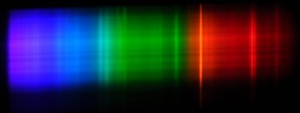
A Cokin P040 diffraction grating (240 lines per mm) was simply placed in front of a DSLR lense (5 Euros only, I was lucky, 40 Euros is a typical price), resulting in the following image:
Since air consists of 80% Nitrogen, 20% Oxygen and a small fraction of Argon, it’s spectrum should be a mix of the spectra of these atoms (some simulated spectra here). But when I look at this spectrum, I find it hard to match them. Also it lacks any hint of yellow tones, to me it is just RG&B.
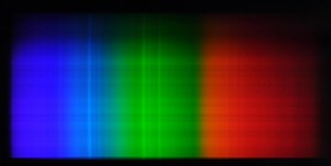
For comparison I have also imaged my Nikon SB-600. I would expect a spectrum similar to Xenon, but also that does not really look like it.
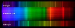
For reference, these are the spectra from Joachim Koppen’s website (http://astro.u-strasbg.fr/~koppen/).
Finally an attempt to match the spectra of the air-gap flash to Oxygen and Nitrogen. It seems that the spectrum mainly consists of Nitrogen (which was to be expected). The simulated spectra of Oxygen en Nitrogen were blurred to match the resolution of the grating/slit photo.
Flash close-up
December 10th, 2011I wanted to see what the flash produces before and during the flash.
While waiting for the trigger the cathode and anode produce a lot of corona and corresponding ultraviolet light.
During the flash a spectrum of oxygen and nitrogen is produced and it seems some copper (green) as well.
The spark also contains a lot of infrared radiation, which causes the red tail in the highlights of some fast moving objects. To my surprise the trace of the spark was very different each flash. It seems Edgerton cut a groove in the inner glass tube to guide the spark.
The gap has 20.000 Volts and a capacitor of 0.05 micro Farads. That equals an energy of 0.5*C*V^2=10 Joules. Since all of that energy is released in about 0.5 microseconds, this means a the flash has a peak power of 20 MegaWatts. Imagine twenty thousand floodlights of 1000 Watts, all illuminating a gap of 20 mm…. That also gives an impression how incredibly short half a microsecond is.
